Antenna-amplifier with BFT 12 for FM-range
The only way to improve the reception of FM-signals or particularly of stereo FM-signals under disadvantageous receiving conditions is to amplify the antenna signal. This should be made directly at the antenna, since the loss is increased meter by meter of any cable. In most cases higher line attenuations can be expected than usually calculated. Even receivers with an additional noise figure of zero do not show any improvements of the signal-to-noise ratio becomes too low because of a long transmission line. Therefore it is practically useless to require extremely low noise figures only for the receivers.
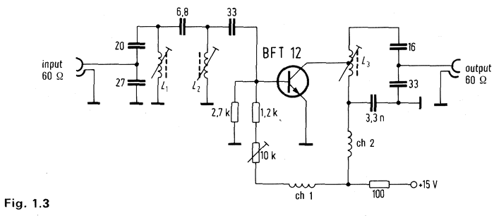
To avoid interferences of signals received from stations of other bands it is propitious to amplify the FM-band only. The band amplifier shown in Fig. 1.3 is connected directly to the 60 ohm output of the FM-antenna, i. e. it is placed at the top of the antenna pole. The matching is achieved by the input band-pass connected to the base of transistor BFT12, being a typically linear silicon transistor for broadband amplifiers. The output filter matched accordingly to a 60 ohm coaxial line is connected to the collector. The operating voltage of 15 V can be supplied by the coaxial line.
Fig. 1.3

Technical data:
- Power gain Gp = 22 db
- Noise figure F = 3.5-4.0 db or 2.2-2.5 KT0
- Input and output reflexion coefficient |r1| and |r0| <= 0.3
- dim(60db) at Vout = 680 mV
- dim(50db) at Vout = 1000 mV
Optimum operating point of minimum intermodulation
Ic =~ 80 mA Vce =~ 7-7.5 V
Supply voltage 15 V
Coil data:
Vogt coil former, ordering code: Sp 3.5/16.6-2048C
Core: U17
- L1 : 5 turns Cu 0.6 mm \o
- L2 : 3 turns Cu 0.6 mm \o
- L3 : 3+2 turns Cu 0.6 mm \o
Choke Ch1 = Ch2: 20 turns Cu L 0.3 mm \o, cross section of winding = 4 mm
Credits –
Antenna-amplifier with BFT 12 for FM-range
from Design Examples of Semiconductor Devices – Siemens


