Erik Grindheim and Engineering Assistant

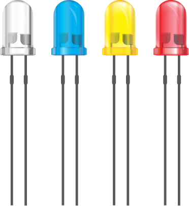
Some projects are Audio VU meters, Serial Port PIC programmer and other interesting articles. The low and high logic levels are displayed by LEDs,which are OFF if the probe tip is floating or connectedto a hi-impedance (>220k) output. A pulse transition isdetected and is indicated by turning on the LED for80 ms.
Logic State Analyzer – The analyzer fetches 300 single bit samples at a select-able rate (in 16 steps from 40 Hz to 1 MHz). It has aprogrammable start at High-to-Low or Low-to-Hightransition at input. Digital waveforms are displayed in apseudographic mode on the LCD
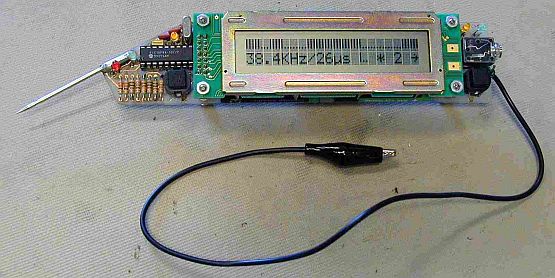
Engineer’s Assistant – Electronic hand-held instrument invented by mr. Voja Antonic. It’s based on Microchip’s PIC16F84 (running at 10 MHz) and a standard 2×20 character LCD-module.
Engineering Assistant Using PIC16F84A
This compact instrument is intended to be a digital lab-oratory tool for hardware and, in some cases, softwaredebugging. It contains four instruments in one unit:logic probe, single channel logic state analyzer, fre-quency counter and serial code receiver.
The only chip used is a PIC16F84A running at 10 MHz.The display unit is a LCD dot matrix alphanumeric mod-ule with 2 rows of 20 characters. The LCD is used asthe display device for all functions, except for the logicprobe which indicates low, high and pulse logic stateson individual LEDs. Mode select, parameter change,function execute and ON/OFF switching is activated bytwo keys.The probe tip is the common input for all functions, andthe GND cable is used for connection to Vss of thetested circuit.


