Instrumentation and Automation – 01

Here are some Test and measurement notes. These ideas come from practical experience. But the jots are not in any order but are quite important.
Scope Notes
- If the waveform on the scope droops then you may need to use a 10X attenuating probe or mode. this attenuator is at the tip of the probe hence better measurement possible, also very high frequency signals may be best transmitted over a 50 ohm impedance matched line to the Oscilloscope.
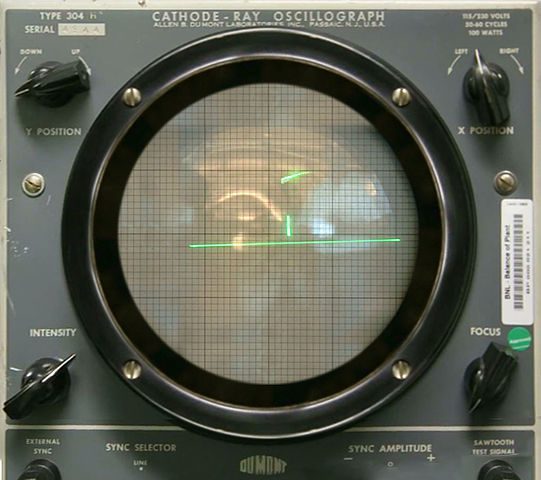
- Karl Ferdinand Braun – In 1897 he built the first cathode-ray tube…oscilloscope. CRT technology is to this day used by most television sets and computer monitors. The CRT is still called the “Braun tube”.
- Do not use an oscilloscope to measure 230V directly, use a transformer, differential probe or attenuator.
- An oscilloscope 1M probe or a DMM 10M impedance can load circuits with nano-pico amps of bias.
DMM Notes
- Test a NPN transistor, DMM in 200K range. emitter negative probe, collector positive probe, it should show open. while still holding that way press wet finger on base and collector, it may show some reading, then it is ok. for PNP swap probes polarity and do the same thing. the wet finger when pressed applies a base current in uA.
- The most common reason of DMM failure is when a person tries to measure 230V AC with a DMM in current or ohms mode, with the probes in the wrong sockets. Use external attenuators and shunts.
- A DMM in diode mode or resistance mode can be used to test IR diodes, take it under 100W lamp and measure, cover the IR diode and measure you will see a response in proper polarity.
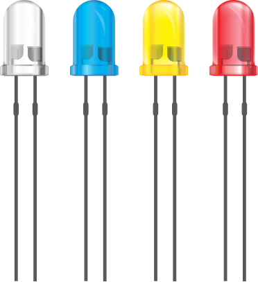
- If you put the DMM in 2V mode and measure the voltage across a ordinary LED near a 40W lamp you will see around 200mV. Turn off 40W lamp the mV will fall near 0. Even metal-can transistors with their top ground away will become photo sensors.
- When you measure low voltages or high resistance like 1M with a DMM your body must not be in contact with the probe tips. Body resistance is low in comparison so error in reading or loading of mV from sensor, in sensitive and high impedance ranges.
- Red socket and probe for positive and black socket and probe for negative
- Is it oscillating ?…. We cannot say, it could also be DC, you need to see if a Clock is present. use a signal tracer or a DMM freq mode, or AC measurement.
- Polarity and Zero Cross indicators tell you to swap the leads. Use a comparator or opamp to build it.


