Voltage regulator 15V 5A Dual Supply
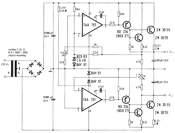
The fig. 6.2 shows the circuit of a regulated power supply for +/- 15 V and 5 A. The output voltages are adjustable between 12 and 17 V.
A tape-wound core transformer is used. It offers a better power-to-volume ratio than conventional ones with laminated cores. The voltage control is achieved by two series transistors, connected in parallel, and by the opamp TAA 761, which acts as control amplifier. For the negative voltage the ground potential serves as reference level for the desired-to-actual value comparison.
The voltage is adjusted by the potentiometers P1 and P2, whereby the center tap of P2 is set firstly to 0. Then both output voltages can be adjusted symmetrically through P1 (range between 12 V and 17 V, for instance).
NPN power-transistors are used as series-control components for the positive as well as negative voltage. Since two transistors 2N3055 have to be connected in parallel for each output voltage, 0.22 ohm resistors are inserted in their emitter leads to achieve a symmetrical load splitting.
Fig. 6.2

Technical data:
Mains voltage …. 220V ±15% 50Hz
Output voltages …. ±15V (adjustable from 12 to 17V)
Max. output current …. 5A each
Max. ambient temperature …. 50 deg C
Mains transformer
Tape-wound core …. 2xSE 130a
Primary windings (220 V) …. n1 = 490 turns, d = 1.0 mm o/
Secundary windings …. n2 = n3 = 50 turns, d2 = d3 = 1.8 mm o/
Ordering code …. B71725-A130-A2
Thermal resistance of heat sinks
for each transistor 2N3055 …. Rth </= 2.5 K/W
for each transistor BD234 …. Rth </= 23 K/W or
for each transistor BDX27 …. Rth </= 38 K/W
Power Supply Circuits – Voltage regulator ± 15 V/5 A
from Design Examples of Semiconductor Devices – Siemens – 1974/75
Did you know ?
Siemens Semiconductors was spun off on April 1 1999 to form a separate legal entity Infineon Technologies AG


